Details
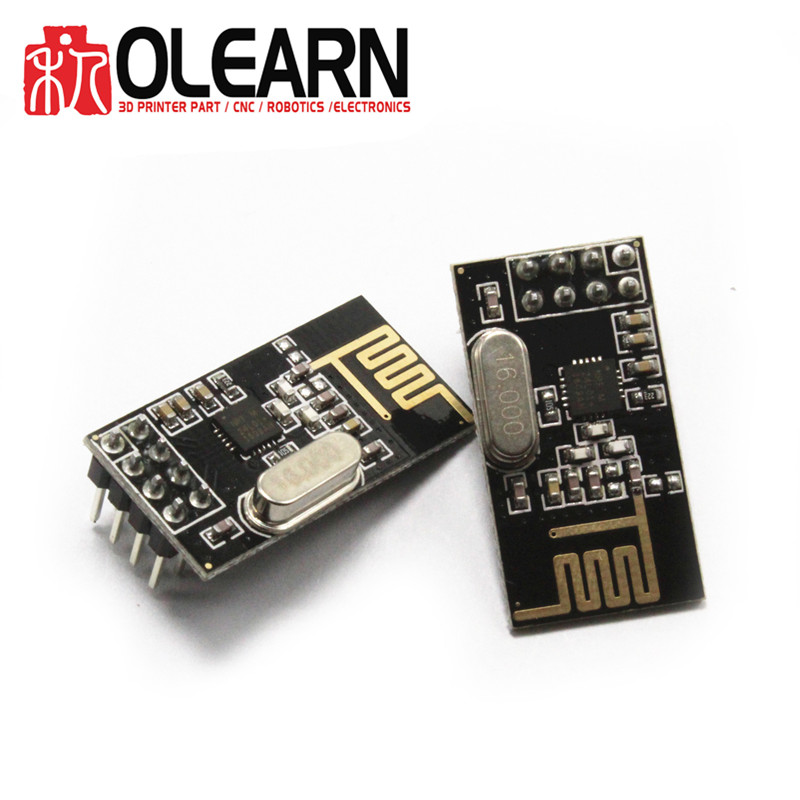
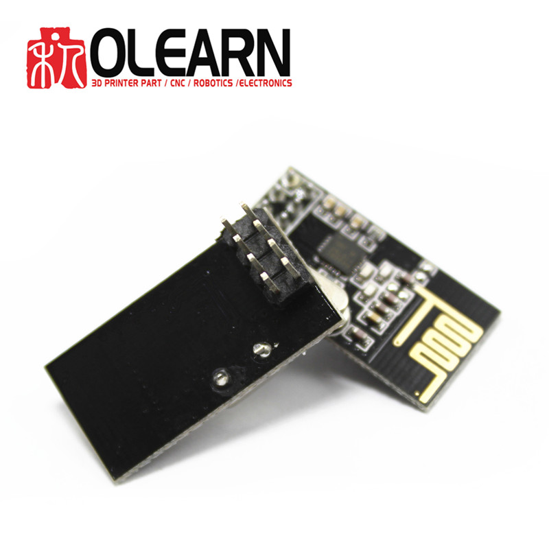
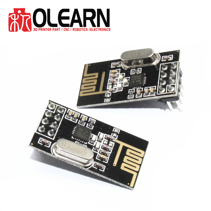
NRF24L01+ 2.4GHz Wireless RF Transceiver Module
Basic Information:
NRF24L01 black
-Maximum operating speeds up to 2Mbps, GFSK modulation efficiency, Anti-interference ability, Particularly suitable for industrial control applications.
-125 Channels, Multi-point communication and frequency hopping to meet the communication needs
-Built-in hardware CRC error detection, Multipoint communication address control.
Low-power 1.9 ~ 3.6V, only 1uA on Power down mode
-Built-in 2.4Ghz antenna
-Available software to set the address, only received local Address when output data(Provide interrupt instruction), can be directly connected to a variety of microcontrollers, Software programming is very convenient.
-Built-in voltage regulator
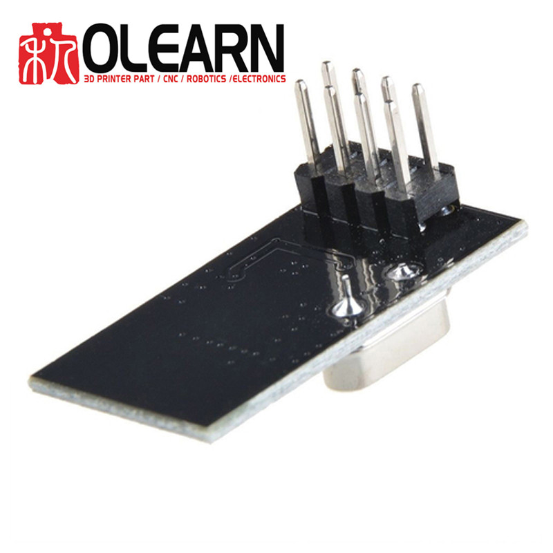
-Standard DIP Pitch Interface for embedded applications
-size: 34mm X 17mm X 1mm on-board AMS1117-3.3 chip
This adapter work great with both versions of the nRF24L01+ (high/low power units). It also work very well with the TMRh20 branch of the RF24 library. You can get this by searching RF24 in the Arduino library manager. Also look at RF24Network, that adds a networking layer on top of RF24, and RF24Mesh that adds a mesh network function on top of RF24Network. The examples with these libraries are very well done and easy to follow.
The issue that you may know is that people have had power delivery problems with the NRF24L01+. Some of the Ardunio boards can not supply enough peak power to both the high and low power units which can cause a whole array of issues (or sometines even causing the NRF24L01+ to not work at all). This adapter solve those issues.
OLEARN Source NRF24L01+ adapter also allow you to swap out radio units quickly without having to remember what pins go to what inputs/outputs, which is a great feature/ perk when using these.
Pin out is as follows (pin1 has the square box, and 2 is across from it etc.)
1 2
3 4
5 6
7 8
Functions as follows:
1: Ground
2: Vcc (3.3v)
3: CE (Chip Enable)
4: CSN (Chip Select Not) Active Low - SPI Chip Select function
5: SCLK (Clock) - SPI Clock Function
6: MOSI (Master Out Slave In) - SPI Data
7: MISO (Master In Slave Out) - SPI Data
8: IRQ (Interrupt) - Optional, but goes low to indicate that data has arrived, fault has occurred, or write buffer full.